"Downhole logging is the process of measuring physical, chemical, and structural properties of penetrated geological formations using logging tools that are either lowered into the borehole on a wireline cable (wireline logging) or placed just behind the drill bit as part of the drill pipe itself (logging-while-drilling). The tools employ various acoustic, nuclear, and electrical measurement techniques to acquire downhole logs of properties such as sonic velocity, density, and electrical resistivity. The wireline cable provides real-time communication between the tools and the surface; logging-while-drilling tools typically record the logs in downhole memory devices, which are subsequently downloaded when the tool returns to the ship.
The downhole logs are rapidly collected, are continuous with depth, and measure in situ properties. They can be interpreted in terms of the formation's stratigraphy, lithology, and mineralogy. The sampling interval is typically 15 cm, with a vertical resolution of about 35 cm. Some tools have a higher sampling interval and resolution; for example, the FMS can electrically image sub-cm-scale features. Logging tools are generally designed to measure formation properties some distance into the formation, in order to minimize the effects of variable borehole diameter and roughness. Logs also provide the major link between borehole and seismic section: sonic velocity logs and checkshots improve depth to travel-time conversion, and synthetic seismograms may be compared directly to the seismic section.
While downhole logs are complementary to core measurements, they also offer certain advantages. In a hole where there is only limited core recovery, the depth location of the incomplete cores can be uncertain; logs provide a continuous depth record of formation properties. Where there is preferential recovery of a certain rock type - for example, basalt pillows can be more easily recovered than breccia -- the logs can reveal a more realistic stratigraphy. The in-situ nature of the downhole measurements is in contrast to measurements on recovered core: when material is no longer under the high-pressure conditions that exist at depth, it can physically expand and gas hydrates can dissociate. The core may also be degraded by the coring process: rotary coring can grind up sediment, resulting in "biscuits" of coherent sediment in a ground-up matrix"


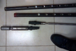
As part of a dummy gas lift
- 1" nose part
- 1" body part with body adapter
Gas Lift Valve Deployment Principle
- Side pocket mandrels allow the deployment and easy retrieval of gas lift valves to control the injection of gas from the casing
- Gas lift valves can be replaced by "Dummy gas lift valves" to plug the holes when not in use
- These Dummy gas lift valves can be turned into measurement locations when one or more of their parts are replaced by a recording sensor
- Nose part to measure tubing pressure
- Body part for casing pressure
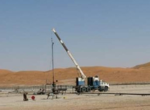
Downhole Live Measurement Deployment


- At the end of a wireline cable used to communicate electrically from sensor to surface
- Casing is used as electrical ground reference if using an insulated slickline cable
- Configuration must be defined with client to suit the cable specs.
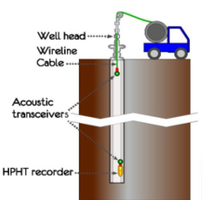
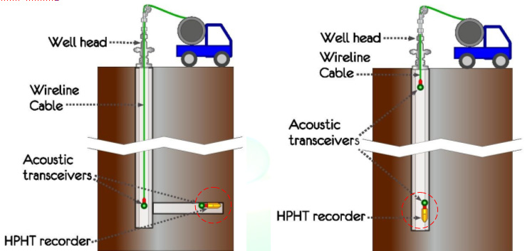
Expected deployment with acoustic communication (in development)
- Sensor communicates acoustically with transceiver a few tens of meters from surface
- Sensor deployed in horizontal segment communicates acoustically with transceiver in the vertical tubing
